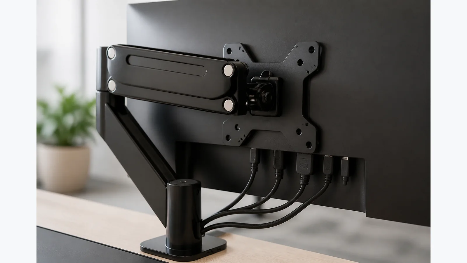
monitor arm blocks monitor ports
Yes - if a monitor arm blocks your monitor ports, treat port clearance as a separate check from VESA compatibility. A matching VESA pattern only tells you the mount holes line up; it does not guarantee that the plate, cable plugs and rear housing will leave enough room for everyday use.
Photograph and label the monitor’s ports before removing the stand
Before you detach the original stand, take a clear photo of every port, cable and connector on the rear of the display. Label the leads if there is any chance of confusion, because once the arm plate is fitted, a blocked socket is much harder to diagnose.
Look for bottom-facing power, DisplayPort, HDMI and USB connections, then note which ones sit closest to the edge of the housing. That gives you a quick reference for the cable path you need to preserve.
Overlay the arm plate footprint on the rear housing
Do not rely on the VESA hole pattern alone. Place the plate outline against the back of the monitor and check how much housing it covers, especially around raised plastic shells, recessed areas and port clusters.
Dell notes that a third-party VESA adapter plate can interfere with the monitor housing and may need manufacturer-appropriate spacing, which is why the surrounding shape matters as much as the hole spacing.
Check connector body and cable-bend clearance, not only the socket opening
Leave room for the connector body, not just the socket opening. A plug can fit the port yet still be unusable if the plate or arm frame sits too close for the cable to bend safely.
VESA standardises the mounting interface, but the display housing and connections remain model-specific. In practice, that means two monitors with the same VESA pattern can still need very different clearance around the rear ports.
Connect difficult bottom-facing cables before final lift only when the monitor manual permits
If the monitor manual allows it, connect hard-to-reach bottom-facing cables before the final lift and tightening stage. If the manual does not permit that order, keep the cables free until the arm is positioned so you do not strain the connectors.
Monitor-arm instructions commonly treat VESA attachment and cable routing as separate installation steps. That is useful here: fit the mount correctly, then route the cables in a way that does not pinch or pull on the plugs.
Test the full arm movement with a loose service loop
After the screen is mounted, move the arm through its full range with a loose service loop in place. Watch for snagging, compression or any point where the cable is forced against the plate or the housing.
This check matters because a setup can look fine at rest and still block ports when the arm swings, rises or lowers. If the cable only works in one position, it is not properly installed.
Reject plate modification, crushed connectors and unsupported adapters
Do not cut, drill or file the plate to create space, and do not crush connectors to make them fit. If a port remains inaccessible, the safer answer is to change the mounting approach rather than force the hardware.
A right-angle adapter should only be used when the exact monitor and signal or power specification permit it. If you are checking a current mount like the M252, the product details show 75 x 75 and 100 x 100 mm VESA support, but the page does not guarantee clearance around every monitor’s ports or publish an exact plate footprint.
For the current product details, see Current product details.